Summary
Each year for the last several years Michael Bergeron of the RPF organises a Secret Santa on the forum. People who sign up are allocated a fellow member to whom they send a small gift (~USD20). In turn each member receives a small gift.
I’ve enjoyed following along the threads for the last few seasons but have always felt a bit intimidated to join in. 2020 was an exceptional year in the negative sense and I felt a little Christmas cheer was in order so I signed up.
This is a detailed post about the gift I made, how I made it, my mistakes and flawed assumptions and the relevant parts/wiring diagram/code I used. I made it in a sort of haphazard fashion but have tried to tie it together in writing. I also forgot to take as many photos as I thought, oops.
Here is a link to the 2020 Secret Santa thread.
Choosing a Gift
After receiving my giftee I went to work looking through their post history to determine what I should get. I discovered a shared love of Captain Jack Sparrow from the Pirates of the Caribbean films.
I’m a big fan of Jack’s compass in the films. I’m working on a project to create a working replica of the compass (maybe that’ll be written up this year, who knows) however with a tight deadline to ship gifts and no workshop that wasn’t going to be ready in time. There was also the added constraint of COVID-19 impacting shipping around the world. Anything I ordered for the project would need to come from local suppliers or it would never arrive in time.
So with these constraints in mind I started looking around. Given the age of the films there wasn’t much to work with – funnily enough people don’t sell props for a franchise that had it’s last film several years ago.
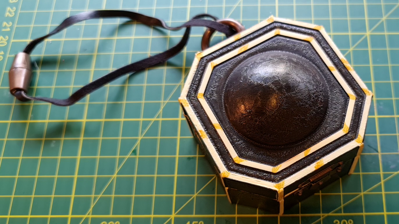
In the end I took a punt and ordered a plastic compass from costumes.com.au. They were based in my state so I figured it shouldn’t take too long to get the compass. Boy was I wrong, it took 10 days for them to ship it and another 10 or so days for it to arrive. I would have just driven the 3 hour round trip to get it had I known it would take that long. Anyway, this is what I had to start with. The listing on that site is now gone but this looks like it on amazon.com.
A quick review
The compass isn’t accurate at all but it looks okay. It’s much smaller than the prop used in the film, Update: it could actually about the same size but taller! See the Amazon listing above for some comparison photos in the reviews. But it is solidly built in a few main parts with injection moulded plastic. Amazingly the bottom of the compass comes off with screws, meaning I can put stuff inside without having to break it open.

It’s not what I’d want for a replica, but for the price it’s about what you’d expect.
What to do with it
Next up I had to work out what to do with it, as I wasn’t happy sending it as it was. Some sort of modification was in order, however without a workshop, time or availability of the usual suppliers it had to be relatively easy and use what I had on hand.
The compass being smaller than anticipated was a real pain, and the compass rose was painted on so I couldn’t do anything with that. But lately I’ve been playing with soundboards so I decided that ‘it wouldn’t be too hard’ (famous last words) to add a sound module so the compass ‘talked’.
What if every time you opened the compass it said a little Jack Sparrow quote? That would be kind-of funny, and a unique gift.
This is a story of failure and compromise under the constraints listed above.
How to do it
Sound module
I did order some sound modules from AlliExpress, however they were never going to arrive in time. Instead, I used a BigDawgGreetings sound module I had on hand. This had the capability to fire off five different sound clips when you push five corresponding buttons. The sounds are loaded into the module via USB cable and proprietary software.
I downloaded the software and it installed fine on my Windows 10 machine however I simply couldn’t get it to work. In hindsight the last time I used these boards I wasn’t on the latest version of Windows, and since then the BigDawg’s website has been updated with a note saying the software is problematic on Windows 10. It should work on Windows XP or 7.
This soundboard was my only option so I tried for a time to load the board by emulating Windows XP in Oracle VM VirtualBox without success. However I did get it to load using emulating Windows 7! The first problem solved!
The sound quality from the board wasn’t great but it’d have to do. Now I think of it I’m not sure what quality settings I had the uploaded switched to, so perhaps I could have made it better. Either way I wouldn’t recommend using these boards unless you need a really simple set up, as more capable boards are available for far less elsewhere.
Sound clips
It wasn’t hard to find sound clips of Jack Sparrow online. I downloaded many clips from movie-sounds.org and moviesoundclips.net.
These were often not ideal, so I imported the clips into Audacity (audio editing software) to do the following:
- Edit clip length
- Add fade-in and fade-out to each end respectively
- Remove or reduce noise and music if possible
- Save as .wav files for the sound module as it can’t take .mp3
I ended up choosing the following quotes:
- ‘My compass is unique’
- ‘Welcome to the Caribbean love’
- ‘Why is the rum always gone?’
- ‘You seem somewhat familiar’
- ‘I feel sullied and unusual’
Controlling the soundboard
Choosing a microcontroller
I could have put five switches on the compass but that wouldn’t be very surprising. I wanted the quotes to fire off at random when the lid was opened so I needed some way to control it and add randomness. Seemed like a good job for a microcontroller.
I had several PICAXE chips on hand, including the small but very useful 08M chip (now unavailable and superceded by the 08M2). This chip has 8 pins, 5 of which can be used for inputs/outputs.
My initial thoughts were to have one pin monitor the lid position (open/close) and then use the others to fire off the sounds. However that only left me with 4 pins for sounds and I really didn’t want to sacrifice the fifth sound given there weren’t many to begin with.
I decided to mount a switch on the lid which controls the power to the microcontroller. When the lid opens the power comes on and the script runs on the microcontroller, triggering the sounds. This effectively gives me another pin and saves power at the same time, as the unit is completely switched off when not in use, instead of in a low power state waiting for an input.
The next challenge came after brushing up on the docs – I discovered only four of the pins could be used as outputs anyway! I really didn’t want to use a bigger microcontroller due to size, price and stubbornness I suppose, although I probably should have. I had both PICAXE 14M2 and 18M2s on hand. Either of them would have made life much easier with many more inputs/outputs and much larger memory capacity, although I wouldn’t have learned nearly as much.
Programming concepts
While I waited for the physical compass to arrive I started noodling about in my microcontroller simulation software, PICAXE VSM. I started with a rough model of the microcontroller and some LEDs to check the logic of my program. In this model leg 3/pin 4 is tied to ground to prevent it floating.

The gist of the program was that on power on it would randomly choose a number from 1-4 and then briefly raise the appropriate pin to a high state to trigger the soundboard, wait a few seconds and then start over.
The RANDOM command generates integers from 0-65535. To get a number from 1 to 4 (later 1 to 5) some simple math is required as stolen from this post:
      random w0         'generate random number to word variable w0
      b2 = w0//4+1      'take the modulus to round the number to 1-4
The code operated as expected, however each time I ran it the same output pin order occurred, it was never random! I made several assumptions here which were incorrect, the first I’ll discuss now.
Randomness in simple microcontrollers
While the simulation seemed to work I couldn’t work out why the randomness wasn’t random. This is just my inexperience showing, as after a bit of searching I discovered these small chips cannot generate random numbers on their own.
As explained on the PICAXE site:
All microcontrollers must perform mathematics to generate random numbers, and so the sequence can never be truly random. On computers a changing quantity (such as the date/time) is used as the start of the calculation, so that each random command is different. The PICAXE does not contain such date functionality, and so the sequence it generates will always be identical unless the value of the word variable is set to a different value before the random command is used.
Or, as user Hippy points out in this forum post:
A register holding the current number is shifted left and the new LSB is set 0 or 1 depending on the settings of other bits (or shift right and set MSB). Each new ‘random number’ can be predicted from its previous and is (for shift left) twice the previous or twice the previous plus one.
The sequence of random numbers generated and the pin selected by my code is as follows.
| Iteration | 0 | 1 | 2 | 3 | 4 | 5 | 6 | 7 | 8 | 9 | 10 |
| Random Value (w0) | 0 | 1 | 2 | 5 | 11 | 23 | 47 | 94 | 189 | 378 | 756 |
| Random Pin (b2) | 0 | 0 | 2 | 3 | 2 | 4 | 4 | 4 | 3 | 2 | 3 |
While this sequence of numbers is random enough, because the program starts from scratch each time the compass lid is opened (when power comes on) it ALWAYS starts with the same number. So it’s not random at all. Oops.
The pseudo random number generator needs to be seeded with something. If it always starts from zero my ‘random’ numbers always have the same sequence because they can’t do anything else. But it can’t be seeded by a fixed number either, or the pattern will just continue from that number instead. We need to have a number come in from outside the controller itself.
Seeding the random number generator
Given I had a spare input pin with no use, that could be used to find a random starting point. This pin also has an 8 bit ADC (analogue to digital converter) so I can measure something and use the measurement as my starting point.
Given what I had in my components box I used a light dependent resistor (LDR) with a voltage divider as my input. The LDR could be placed somewhere on the compass where it gets enough light to get a reading.
The ADC value was used as the seed, the random command was run twice to get a big number and then divided to get a result of 1-4. It worked in the simulation, but it couldn’t be truly random as the input value on the LDR was fixed. This would come later in testing.
Adding more outputs
So, how to increase the I/O capacity of this little controller to trigger my five buttons? A bit of searching revealed the best way for this chip was to use a 74HC595 chip – a serial-in-to-parallel-out chip. This chip has 16 pins, 8 of which can be used as outputs. You can also daisy chain them for many more outputs. Eight outputs is more than I need but it’ll do. As a plus I could buy one at my local electronics store.
The 74HC595 works by taking an 8 bit serial input from the PICAXE and when ‘latched’ updating it’s output pins to match. A good explainer can be found here.
I found some code on the PICAXE forums (the best place for information on PICAXE) on how to get the 08M to talk to the 74HC595. This code is for two 74HC595s daisy chained but I modified the code to limit it to 8 bit output instead of 16 bits.
I wrote up the code and added the 74HC595 to my VSM model to test it along with the LDR. It was working!

Breadboarding
The next step was to bust out my PICAXE download board and cable, and the breadboard to test the circuit in reality. This was the first real test and I ran into heaps of problems which I’ll summarise as this article is already double the length I intended.
Interfacing with the BigDawg sound module
The sound module comes with five small push button switches, each hooked up to two pins on the board. I measured the voltages on each of these pins and one was about 3.5V and the other was 0V. The switch closed these two pins, so I assumed to trigger the board I’d have to raise the 0V pin to 3.5V, which I could do with the output from my circuit.

This didn’t work. I busted out my logic probe to check each pin on the circuit was going high/low as required (after adding a bunch of delays to the program so I had time to see it run) and it seemed to be working, but the soundboard wasn’t responding. I decided I couldn’t interface with the board directly and chose another path.
Optoisolators
Opto-isolators are ingenious little devices that basically act like logic powered switches. They contain two circuits that are electrically isolated from one another, but powering one switches on the other. How? Powering the first lights up an internal LED which shines on a phototransistor, which then allows current to flow on the other side.
I happened to have several ACPL-824 two channel optocouplers on hand. At first I wired them up without current-limiting resistors because I am a n00b with electronics but luckily found this forum post with an example of the wiring so didn’t burn them out.


With the optoisolators running it sort of worked! It wasn’t reliable though. It didn’t work every time it was triggered.
Getting the wiring correct
Why was this not reliable? Everything seemed to be wired up correctly. That was until I found a post on picaxeforum.co.uk (which I sadly can no longer find) that gave me the info I was missing – the 74HC595 needed pull-up and pull-down resistors on two pins to have it set up correctly. Coincidentally the same thread also dealt with a sound board and the user’s board required a logic low to trigger, where I assumed I needed a logic high.
I tested this and it worked! This meant I could get rid of the optoisolators which was great as I needed the space inside the compass. I updated the code to have all outputs high then drop one to low randomly. Everything was finally coming together. I updated my circuit diagram and simulation so I had it written down, then moved on to getting it into the compass.
Fabricating the board
Next up was moving off the breadboard and onto a smaller board. I didn’t have the time or skills to create a PCB so I used strip-board instead. I wasted some time trying to find a way to plan the board automatically using my wiring schematic without success so I just sort of winged it.
I started by designating the top strip a power rail and the bottom strip the ground rail, then immediately screwed that up by soldering one of the chips in the wrong place. From there I just made do, progressively adding components as I referred to the wiring diagram and breadboard.
The final PICAXE 08M board ended up being 25mm x 40mm.
Assembly
The last challenge involved stuffing everything inside the compass. This was much trickier than I expected. Here are the mods I made to get things to fit.
The compass case
To make more room, I used a pair of side cutters to remove the gussets and other supports from inside the compass, then cleaned it up with an exacto knife. That gave me a little more room.

The sound module
Even after cutting out the internal supports in the plastic case the soundboard only just fit inside. The board came with 3 × 1.5V button cells in cages soldered to it, so I removed those and attached wires to power it from the lid switch. This thinned the board down a bit.
I also removed the USB plug as this added about 0.5mm to the length of the board and that helped it slide inside the compass much easier.
During all the prototyping the speaker wires detached from both the board and speaker itself so I soldered some pins to the board so I could use a slightly better speaker with heavier wire.
If I had more time or a spare soundboard I would have trimmed the soundboard itself down a bit, but I’d already modified it a bit and didn’t want to break it.
Power
I was planning on using 3 × AAA batteries to run the unit, however I just couldn’t make them fit with everything else. None of the standard AAA enclosures would work while also allowing everything else to fit. After ages of trying different setups, including heavily modifying a 3 AAA enclosure from a lamp I gave up on the AAA idea.
I turned to button cells, and futzed about with them for a time until I bit the bullet and got two coin cell holders and put 3V lithium batteries in them. The 6V was too much but the circuit worked so I’ll call that done.
Lid switch and LDR
The lid switch was a small microswitch that I superglued just under the lid catch. The tabs on the lid poked through the holes in the body about 1mm, so there wasn’t much room for error but the microswitch was easy to tell when it was engaged or not.
Next time I won’t use superglue though! The glue was so fine it ran inside the switch, binding up the mechanism. I had to rip it out again. Given it was late at night and I didn’t have a spare on hand I meticulously pulled the switch apart and managed to get it going again. NOT RECOMMENDED.
The LDR was similarly glued under one of the tab holes with hot glue.
Final fit
Then it was just a matter of trying to stuff everything in in the correct order so they weren’t smashing into each other too hard when I screwed on the base.

Then, the moment of truth, does it work? Yes! Thank goodness.
All working as intended. Open the lid, a pseudo random clip from the films plays.
I was very happy to have pulled this together with two weeks left to ship it to my secret santa for Christmas! It was in the mail the next day, sadly it took 3.5 weeks to get there with the COVID-19 delays, but the recipient enjoyed it nonetheless.
Lessons learned
- I’m unhappy about the coin cell battery holders, they were meant for PCB mount and I should have soldered them down to stripboard.
- Next time I’ll use finer wire to connect stuff – the wire used should be sturdy but also made squishing things in difficult.
- I’m probably not using the BigDawg sound modules again, they are far bigger, more expensive and harder to use than other modules on the market (although they do come with batteries and a speaker)
- The PICAXE can be quite powerful even in a tiny 8 pin package, they are great chips – the 08M2 is even better with 6 input/outputs!
Build documentation
Wiring diagram

Code running on the 08M
'NOTES
'This program is for the Jack Sparrow talking compass project as described at propdroid.com/making-a-jack-sparrow-talking-compass
'It sets a random pin high on a 74HC595 via serial connection to activate a channel on the sound module
'Written by Martin Goddard @propdroid with code copied from users at picaxeforums.co.uk as credited on propdroid.com

initiate:
low c.0
low c.1
low c.2
'Set all pins of 74HC595 high

for b5 = 1 to 8
	high c.1
	high c.0 'set pin high for rising edge trigger to store data
	low c.0  'reset pin after data stored
next
high c.2       'send rising edge trigger to latch data
low c.2        'reset pin after latch
low c.1
low c.0

pause 250
'Read light sensor on ADC C.4 to prime random integer
readadc C.4,b3

main:

random w1
random w1
b2 = w1//5+1

select case b2
case 1
	b0 = %11111110
	gosub sendData
case 2
	b0 = %11111101
	gosub sendData
case 3
	b0 = %11111011
	gosub sendData
case 4
	b0 = %11110111
	gosub sendData
case 5
	b0 = %11101111
	gosub sendData
end select

pause 10000
goto initiate

end

sendData:		'Send data to 74HC595 chip
low c.0
low c.1
low c.2
	for b4 = 1 to 8
		if bit0 = 0 then 'set bit for transmit
			low c.1
		else
			high c.1
	endif
		high c.0	'set pin high for rising edge trigger to store data
		low c.0	'reset pin after data stored
		b0=b0/2	'shift bits to right one place

	next
	high c.2      	'send rising edge trigger to latch data
	low c.2       	'reset pin after latch

pause 100

low c.0
low c.1
low c.2
return
Bill of Materials
| Category | Reference | Value | Order Code |
| Resistors | “R1” | 10k | RES10K |
| Resistors | “R3” | 10k | RES10K |
| Resistors | “R4” | 10k | RES10K |
| Resistors | “R5” | 10k | RES10K |
| Resistors | “R6” | 10k | RES10K |
| Resistors | “R7” | 10k | RES10K |
| Resistors | “R8” | 10k | RES10K |
| Resistors | “R9” | 10k | RES10K |
| Resistors | “R10” | 10k | RES10K |
| Resistors | “R11” | 10k | RES10K |
| Resistors | “R2” | 22k | RES22K |
| Capacitors | “C1” | 100n | CAP001 |
| Integrated Circuits | “U1” | PICAXE08M-IC | AXE007M |
| Integrated Circuits | “U2” | 74HC595 | |
| Miscellaneous | “CT1” | PICAXE SOCKET | CON039 |
| Miscellaneous | “LDR1” | LDR | SEN002 |
| Miscellaneous | “LS1” | BIG DAWG SPEAKER | SPE010 |
| Miscellaneous | “SW1” | SW-SPST-MOM | |
| Miscellaneous | Enclosure | Jack Sparrow Compass |